- 您现在的位置:买卖IC网 > Sheet目录3882 > PIC18F442T-E/ML (Microchip Technology)IC MCU FLASH 8KX16 EE A/D 44QFN
Micrel, Inc.
KSZ8864RMN
April 2012
14
M9999-043012-1.5
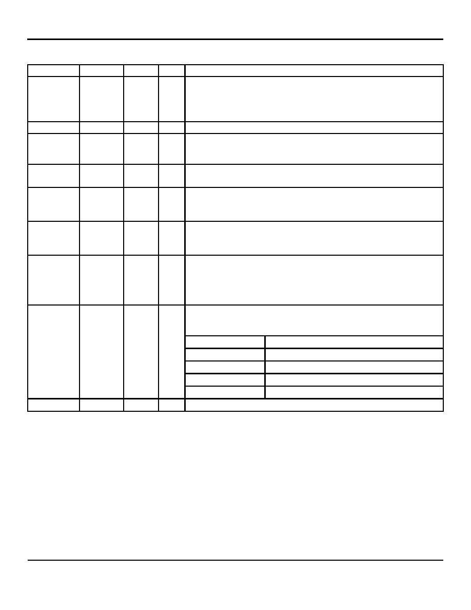
Pin Description (Continued)
Pin Number
Pin Name
Type
(1)
Port
Pin Function
(2)
52
P1LED0
IPU/O
1
LED indicator for Port 1.
Strap option: for Switch MAC4 only.
PU (default) = Select MII interface for the Switch MAC4 SW4-MII.
PD = Select RMII interface for the Switch MAC4 SW4-RMII.
53
MDC
IPU
All
MII management interface clock. Or SMI interface clock
54
MDIO
IPU/O
All
MII management data I/O. Or SMI interface data I/O
Features internal pull down to define pin state when not driven.
Note: Need an external pull-up when driven.
55
SPIQ
IPU/O
All
SPI serial data output in SPI slave mode.
Note: Need an external pull-up when driven.
56
SPIC/SCL
IPU/O
All
(1) Input clock up to 25MHz in SPI slave mode,
(2) output clock at 61KHz in I
2C master mode.
Note: Need an external pull-up when driven.
57
SPID/SDA
IPU/O
All
(1) Serial data input in SPI slave mode;
(2) serial data input/output in I
2C master mode.
Note: Need an external pull-up when driven.
58
SPIS_N
IPU
All
Active low.
(1) SPI data transfer start in SPI slave mode. When SPIS_N is high, the device is
deselected and SPIQ is held in high impedance state, a high-to-low transition to
initiate the SPI data transfer.
(2) Not used in I
2C master mode.
Serial bus configuration pin.
For this case, if the EEPROM is not present, the Switch will start itself with the
PS[1.0] = 00 default register values.
Pin Configuration
Serial Bus Configuration
PS[1.0]=00
I
2C Master Mode for EEPROM
PS[1.0]=01
SMI Interface Mode
PS[1.0]=10
SPI Slave Mode for CPU Interface
59
PS1
IPD
PS[1.0]=11
Factory Test Mode (BIST)
60
PS0
IPD
Serial bus configuration pin.
发布紧急采购,3分钟左右您将得到回复。
相关PDF资料
PIC18LF4539T-I/ML
IC MCU FLASH 12KX16 EE A/D 44QFN
PIC18F452T-E/ML
IC MCU FLASH 16KX16 A/D 44QFN
PIC18F442-E/ML
IC MCU FLASH 8KX16 EE A/D 44QFN
PIC18F2539T-I/SO
IC MCU FLASH 12KX16 EE AD 28SOIC
PIC18F4439T-I/PT
IC MCU FLASH 6KX16 EE A/D 44TQFP
PIC16LF77T-I/ML
IC MCU FLASH 8KX14 A/D 44QFN
PIC16F74T-E/ML
IC MCU FLASH 4KX14 A/D 44QFN
PIC16F74-E/ML
IC MCU FLASH 4KX14 A/D 44QFN
相关代理商/技术参数
PIC18F442T-I/L
功能描述:8位微控制器 -MCU 16KB 768 RAM 34I/O RoHS:否 制造商:Silicon Labs 核心:8051 处理器系列:C8051F39x 数据总线宽度:8 bit 最大时钟频率:50 MHz 程序存储器大小:16 KB 数据 RAM 大小:1 KB 片上 ADC:Yes 工作电源电压:1.8 V to 3.6 V 工作温度范围:- 40 C to + 105 C 封装 / 箱体:QFN-20 安装风格:SMD/SMT
PIC18F442T-I/ML
功能描述:8位微控制器 -MCU 16KB 768 RAM 34I/O RoHS:否 制造商:Silicon Labs 核心:8051 处理器系列:C8051F39x 数据总线宽度:8 bit 最大时钟频率:50 MHz 程序存储器大小:16 KB 数据 RAM 大小:1 KB 片上 ADC:Yes 工作电源电压:1.8 V to 3.6 V 工作温度范围:- 40 C to + 105 C 封装 / 箱体:QFN-20 安装风格:SMD/SMT
PIC18F442T-I/PT
功能描述:8位微控制器 -MCU 16KB 768 RAM 34I/O RoHS:否 制造商:Silicon Labs 核心:8051 处理器系列:C8051F39x 数据总线宽度:8 bit 最大时钟频率:50 MHz 程序存储器大小:16 KB 数据 RAM 大小:1 KB 片上 ADC:Yes 工作电源电压:1.8 V to 3.6 V 工作温度范围:- 40 C to + 105 C 封装 / 箱体:QFN-20 安装风格:SMD/SMT
PIC18F4431-E/ML
功能描述:8位微控制器 -MCU 16KB 768 RAM 34 I/O RoHS:否 制造商:Silicon Labs 核心:8051 处理器系列:C8051F39x 数据总线宽度:8 bit 最大时钟频率:50 MHz 程序存储器大小:16 KB 数据 RAM 大小:1 KB 片上 ADC:Yes 工作电源电压:1.8 V to 3.6 V 工作温度范围:- 40 C to + 105 C 封装 / 箱体:QFN-20 安装风格:SMD/SMT
PIC18F4431-E/P
功能描述:8位微控制器 -MCU 16KB 768 RAM 34 I/O RoHS:否 制造商:Silicon Labs 核心:8051 处理器系列:C8051F39x 数据总线宽度:8 bit 最大时钟频率:50 MHz 程序存储器大小:16 KB 数据 RAM 大小:1 KB 片上 ADC:Yes 工作电源电压:1.8 V to 3.6 V 工作温度范围:- 40 C to + 105 C 封装 / 箱体:QFN-20 安装风格:SMD/SMT
PIC18F4431-E/P
制造商:Microchip Technology Inc 功能描述:IC 8BIT FLASH MCU 18F4431 DIP40
PIC18F4431-E/PT
功能描述:8位微控制器 -MCU 16KB 768 RAM 34 I/O RoHS:否 制造商:Silicon Labs 核心:8051 处理器系列:C8051F39x 数据总线宽度:8 bit 最大时钟频率:50 MHz 程序存储器大小:16 KB 数据 RAM 大小:1 KB 片上 ADC:Yes 工作电源电压:1.8 V to 3.6 V 工作温度范围:- 40 C to + 105 C 封装 / 箱体:QFN-20 安装风格:SMD/SMT
PIC18F4431-E/PT
制造商:Microchip Technology Inc 功能描述:IC 8BIT FLASH MCU 18F4431 TQFP44